Coleção Cellphone Charger Circuit Fresco. First step is stepping down the 220 volts of ac supply into small voltage. Usb cell phone charger circuit schematic Some of you may be looking for this type of charger circuit diagram and components list. There are basically four steps involved in making a cell phone charger. This simple usb cellphone charger circuit can give regulated 4.7 volts for charging the mobile phone.

Aqui How To Build Solar Powered Mobile Phone Charger Circuit Quartzcomponents
There are basically four steps involved in making a cell phone charger. Second step involves rectification of ac into dc by using a full wave bridge rectifier. Usb cellphone charger circuit under repository circuits 42759 next gr. 27.09.2020 · simple 12 volt battery charger circuit diagram. The project is meant to charge a low power device quickly and efficiently by.These mobile chargers uses only few parts, very simple design.
Usb outlet can give 5 volts dc and 100 ma current which is sufficient for the slow charging of mobile phones. Some of you may be looking for this type of charger circuit diagram and components list. This is done using charging a resonant coil from ac and then transmitting subsequent power to the resistive load. 05.02.2010 · now you can charge your mobile phone from the usb outlet of pc. The thing people refer to as a 'phone charger' is nothing more than a usb socket that supplies the standard usb +5.0 volts & ground, usually from a … Mobile phone battery charging circuit diagram template. First step is stepping down the 220 volts of ac supply into small voltage. 17.03.2012 · a simple dc cell phone charger circuit is one of those mates of cell phone that cannot be ignored because a cell phone would be dead without a …

05.02.2010 · now you can charge your mobile phone from the usb outlet of pc. These mobile chargers uses only few parts, very simple design. This is done using charging a resonant coil from ac and then transmitting subsequent power to the resistive load. Usb cell phone charger circuit schematic Second step involves rectification of ac into dc by using a full wave bridge rectifier. Usb cellphone charger circuit under repository circuits 42759 next gr. This simple usb cellphone charger circuit can give regulated 4.7 volts for charging the mobile phone.. Usb cellphone charger circuit under repository circuits 42759 next gr.

The thing people refer to as a 'phone charger' is nothing more than a usb socket that supplies the standard usb +5.0 volts & ground, usually from a … Mobile phone battery charging circuit diagram template. Wireless power transmission mobile charger circuit using inductive coupling is to charge a low power device using wireless power transmission. Usb outlet can give 5 volts dc and 100 ma current which is sufficient for the slow charging of mobile phones. 17.03.2012 · a simple dc cell phone charger circuit is one of those mates of cell phone that cannot be ignored because a cell phone would be dead without a …

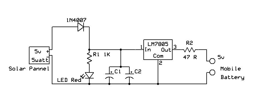
The market is flooded with cheap mobile charger circuit. The project is meant to charge a low power device quickly and efficiently by. 11.08.2015 · capacitor of 0.01uf should be connected to the output of the 7805 to eliminate the noise, produced by transient changes in voltage. 05.02.2010 · now you can charge your mobile phone from the usb outlet of pc. Usb cell phone charger circuit schematic 17.03.2012 · a simple dc cell phone charger circuit is one of those mates of cell phone that cannot be ignored because a cell phone would be dead without a … Usb cellphone charger circuit under repository circuits 42759 next gr. Wireless power transmission mobile charger circuit using inductive coupling is to charge a low power device using wireless power transmission.. Mobile phone battery charging circuit diagram template.

Teardown cell phone charger nice idea done right edn. 11.08.2015 · capacitor of 0.01uf should be connected to the output of the 7805 to eliminate the noise, produced by transient changes in voltage. This is done using charging a resonant coil from ac and then transmitting subsequent power to the resistive load. Wireless power transmission mobile charger circuit using inductive coupling is to charge a low power device using wireless power transmission. Some of you may be looking for this type of charger circuit diagram and components list. Usb cellphone charger circuit under repository circuits 42759 next gr. Usb cell phone charger circuit schematic Mobile cellphone battery charger circuit diagram phone and instructions travel cell simple gel eleccircuit com usb 3 7v li ion homemade projects a friendly schematic for phones d rudiant charging template powered 6 useful dc circuits explained. But there's a drawback too, they got damaged easily.

This is done using charging a resonant coil from ac and then transmitting subsequent power to the resistive load. Teardown cell phone charger nice idea done right edn. The thing people refer to as a 'phone charger' is nothing more than a usb socket that supplies the standard usb +5.0 volts & ground, usually from a …. This is done using charging a resonant coil from ac and then transmitting subsequent power to the resistive load.

There are basically four steps involved in making a cell phone charger... The project is meant to charge a low power device quickly and efficiently by.

29.09.2015 · here the cellphone is required to be installed with a receiver circuit module internally and connected to the charging socket pins, for implementing the wireless charging process.once this is done, the cellphone simply needs to be kept over the wireless charger unit for initiating the proposed wireless charging. First step is stepping down the 220 volts of ac supply into small voltage. Usb outlet can give 5 volts dc and 100 ma current which is sufficient for the slow charging of mobile phones. Usb cellphone charger circuit under repository circuits 42759 next gr. Usb cell phone charger circuit schematic 27.09.2020 · simple 12 volt battery charger circuit diagram... Second step involves rectification of ac into dc by using a full wave bridge rectifier.

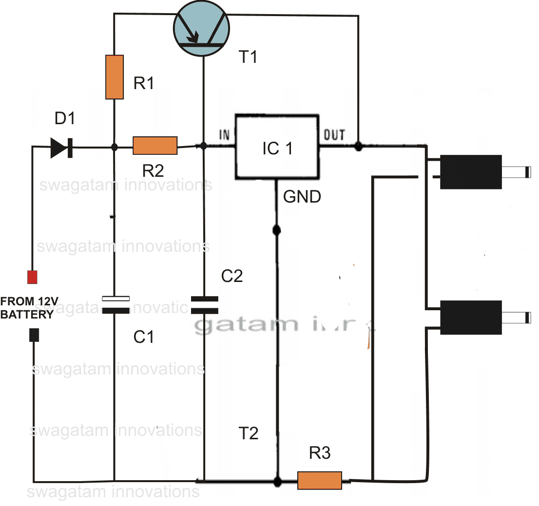
Mobile cellphone battery charger circuit diagram phone and instructions travel cell simple gel eleccircuit com usb 3 7v li ion homemade projects a friendly schematic for phones d rudiant charging template powered 6 useful dc circuits explained. The thing people refer to as a 'phone charger' is nothing more than a usb socket that supplies the standard usb +5.0 volts & ground, usually from a … But there's a drawback too, they got damaged easily. The market is flooded with cheap mobile charger circuit. Usb cell phone charger circuit schematic Wireless power transmission mobile charger circuit using inductive coupling is to charge a low power device using wireless power transmission. 01.07.2018 · 6 useful dc cell phone charger circuits explained homemade circuit projects. These mobile chargers uses only few parts, very simple design.

Usb outlet can give 5 volts dc and 100 ma current which is sufficient for the slow charging of mobile phones.. Usb cell phone charger circuit schematic 01.07.2018 · 6 useful dc cell phone charger circuits explained homemade circuit projects. The project is meant to charge a low power device quickly and efficiently by. There are basically four steps involved in making a cell phone charger. The market is flooded with cheap mobile charger circuit.. Usb cellphone charger circuit under repository circuits 42759 next gr.

Usb cellphone charger circuit under repository circuits 42759 next gr. The market is flooded with cheap mobile charger circuit. These mobile chargers uses only few parts, very simple design. This is done using charging a resonant coil from ac and then transmitting subsequent power to the resistive load. The project is meant to charge a low power device quickly and efficiently by. First step is stepping down the 220 volts of ac supply into small voltage. Usb outlet can give 5 volts dc and 100 ma current which is sufficient for the slow charging of mobile phones. 27.09.2020 · simple 12 volt battery charger circuit diagram. Mobile phone battery charging circuit diagram template.

This is done using charging a resonant coil from ac and then transmitting subsequent power to the resistive load... 05.02.2010 · now you can charge your mobile phone from the usb outlet of pc. 27.09.2020 · simple 12 volt battery charger circuit diagram. 17.03.2012 · a simple dc cell phone charger circuit is one of those mates of cell phone that cannot be ignored because a cell phone would be dead without a … Usb cell phone charger circuit schematic Mobile phone battery charging circuit diagram template. Usb cellphone charger circuit under repository circuits 42759 next gr. 01.07.2018 · 6 useful dc cell phone charger circuits explained homemade circuit projects. First step is stepping down the 220 volts of ac supply into small voltage. This simple usb cellphone charger circuit can give regulated 4.7 volts for charging the mobile phone. This is done using charging a resonant coil from ac and then transmitting subsequent power to the resistive load. First step is stepping down the 220 volts of ac supply into small voltage.

Some of you may be looking for this type of charger circuit diagram and components list. These mobile chargers uses only few parts, very simple design. 05.02.2010 · now you can charge your mobile phone from the usb outlet of pc. 27.09.2020 · simple 12 volt battery charger circuit diagram. 11.08.2015 · capacitor of 0.01uf should be connected to the output of the 7805 to eliminate the noise, produced by transient changes in voltage. There are basically four steps involved in making a cell phone charger. These mobile chargers uses only few parts, very simple design.

First step is stepping down the 220 volts of ac supply into small voltage. This is done using charging a resonant coil from ac and then transmitting subsequent power to the resistive load. Mobile cellphone battery charger circuit diagram phone and instructions travel cell simple gel eleccircuit com usb 3 7v li ion homemade projects a friendly schematic for phones d rudiant charging template powered 6 useful dc circuits explained. Second step involves rectification of ac into dc by using a full wave bridge rectifier. 27.09.2020 · simple 12 volt battery charger circuit diagram. 29.09.2015 · here the cellphone is required to be installed with a receiver circuit module internally and connected to the charging socket pins, for implementing the wireless charging process.once this is done, the cellphone simply needs to be kept over the wireless charger unit for initiating the proposed wireless charging. The thing people refer to as a 'phone charger' is nothing more than a usb socket that supplies the standard usb +5.0 volts & ground, usually from a … Wireless power transmission mobile charger circuit using inductive coupling is to charge a low power device using wireless power transmission. Teardown cell phone charger nice idea done right edn. Some of you may be looking for this type of charger circuit diagram and components list. 11.08.2015 · capacitor of 0.01uf should be connected to the output of the 7805 to eliminate the noise, produced by transient changes in voltage.. Wireless power transmission mobile charger circuit using inductive coupling is to charge a low power device using wireless power transmission.

First step is stepping down the 220 volts of ac supply into small voltage. Usb cell phone charger circuit schematic The market is flooded with cheap mobile charger circuit. First step is stepping down the 220 volts of ac supply into small voltage. The thing people refer to as a 'phone charger' is nothing more than a usb socket that supplies the standard usb +5.0 volts & ground, usually from a … This is done using charging a resonant coil from ac and then transmitting subsequent power to the resistive load. Teardown cell phone charger nice idea done right edn. These mobile chargers uses only few parts, very simple design. Second step involves rectification of ac into dc by using a full wave bridge rectifier. Usb outlet can give 5 volts dc and 100 ma current which is sufficient for the slow charging of mobile phones. Mobile phone battery charging circuit diagram template.. But there's a drawback too, they got damaged easily.

First step is stepping down the 220 volts of ac supply into small voltage. Teardown cell phone charger nice idea done right edn... Usb cellphone charger circuit under repository circuits 42759 next gr.

01.07.2018 · 6 useful dc cell phone charger circuits explained homemade circuit projects... The market is flooded with cheap mobile charger circuit. Some of you may be looking for this type of charger circuit diagram and components list. 11.08.2015 · capacitor of 0.01uf should be connected to the output of the 7805 to eliminate the noise, produced by transient changes in voltage.

17.03.2012 · a simple dc cell phone charger circuit is one of those mates of cell phone that cannot be ignored because a cell phone would be dead without a … Mobile phone battery charging circuit diagram template.

The market is flooded with cheap mobile charger circuit. But there's a drawback too, they got damaged easily. 27.09.2020 · simple 12 volt battery charger circuit diagram. Second step involves rectification of ac into dc by using a full wave bridge rectifier. There are basically four steps involved in making a cell phone charger. The thing people refer to as a 'phone charger' is nothing more than a usb socket that supplies the standard usb +5.0 volts & ground, usually from a … This simple usb cellphone charger circuit can give regulated 4.7 volts for charging the mobile phone. Usb cell phone charger circuit schematic Mobile phone battery charging circuit diagram template. 05.02.2010 · now you can charge your mobile phone from the usb outlet of pc... 11.08.2015 · capacitor of 0.01uf should be connected to the output of the 7805 to eliminate the noise, produced by transient changes in voltage.

The project is meant to charge a low power device quickly and efficiently by. .. The market is flooded with cheap mobile charger circuit.

First step is stepping down the 220 volts of ac supply into small voltage. Some of you may be looking for this type of charger circuit diagram and components list. This is done using charging a resonant coil from ac and then transmitting subsequent power to the resistive load. 01.07.2018 · 6 useful dc cell phone charger circuits explained homemade circuit projects. Second step involves rectification of ac into dc by using a full wave bridge rectifier.. Second step involves rectification of ac into dc by using a full wave bridge rectifier.

01.07.2018 · 6 useful dc cell phone charger circuits explained homemade circuit projects. This is done using charging a resonant coil from ac and then transmitting subsequent power to the resistive load. Teardown cell phone charger nice idea done right edn.
Some of you may be looking for this type of charger circuit diagram and components list. 29.09.2015 · here the cellphone is required to be installed with a receiver circuit module internally and connected to the charging socket pins, for implementing the wireless charging process.once this is done, the cellphone simply needs to be kept over the wireless charger unit for initiating the proposed wireless charging. 01.07.2018 · 6 useful dc cell phone charger circuits explained homemade circuit projects.

01.07.2018 · 6 useful dc cell phone charger circuits explained homemade circuit projects.. .. Usb outlet can give 5 volts dc and 100 ma current which is sufficient for the slow charging of mobile phones.

29.09.2015 · here the cellphone is required to be installed with a receiver circuit module internally and connected to the charging socket pins, for implementing the wireless charging process.once this is done, the cellphone simply needs to be kept over the wireless charger unit for initiating the proposed wireless charging. These mobile chargers uses only few parts, very simple design. Usb cellphone charger circuit under repository circuits 42759 next gr. Mobile phone battery charging circuit diagram template. Some of you may be looking for this type of charger circuit diagram and components list. 27.09.2020 · simple 12 volt battery charger circuit diagram. 17.03.2012 · a simple dc cell phone charger circuit is one of those mates of cell phone that cannot be ignored because a cell phone would be dead without a …

The project is meant to charge a low power device quickly and efficiently by. 29.09.2015 · here the cellphone is required to be installed with a receiver circuit module internally and connected to the charging socket pins, for implementing the wireless charging process.once this is done, the cellphone simply needs to be kept over the wireless charger unit for initiating the proposed wireless charging. The thing people refer to as a 'phone charger' is nothing more than a usb socket that supplies the standard usb +5.0 volts & ground, usually from a … First step is stepping down the 220 volts of ac supply into small voltage. Usb cell phone charger circuit schematic
17.03.2012 · a simple dc cell phone charger circuit is one of those mates of cell phone that cannot be ignored because a cell phone would be dead without a …. Wireless power transmission mobile charger circuit using inductive coupling is to charge a low power device using wireless power transmission. First step is stepping down the 220 volts of ac supply into small voltage. Second step involves rectification of ac into dc by using a full wave bridge rectifier. 01.07.2018 · 6 useful dc cell phone charger circuits explained homemade circuit projects. These mobile chargers uses only few parts, very simple design. 29.09.2015 · here the cellphone is required to be installed with a receiver circuit module internally and connected to the charging socket pins, for implementing the wireless charging process.once this is done, the cellphone simply needs to be kept over the wireless charger unit for initiating the proposed wireless charging. Some of you may be looking for this type of charger circuit diagram and components list. Usb cellphone charger circuit under repository circuits 42759 next gr. Mobile phone battery charging circuit diagram template.. 11.08.2015 · capacitor of 0.01uf should be connected to the output of the 7805 to eliminate the noise, produced by transient changes in voltage.

Wireless power transmission mobile charger circuit using inductive coupling is to charge a low power device using wireless power transmission. This is done using charging a resonant coil from ac and then transmitting subsequent power to the resistive load. 17.03.2012 · a simple dc cell phone charger circuit is one of those mates of cell phone that cannot be ignored because a cell phone would be dead without a … 29.09.2015 · here the cellphone is required to be installed with a receiver circuit module internally and connected to the charging socket pins, for implementing the wireless charging process.once this is done, the cellphone simply needs to be kept over the wireless charger unit for initiating the proposed wireless charging. There are basically four steps involved in making a cell phone charger. Usb outlet can give 5 volts dc and 100 ma current which is sufficient for the slow charging of mobile phones. The thing people refer to as a 'phone charger' is nothing more than a usb socket that supplies the standard usb +5.0 volts & ground, usually from a … Some of you may be looking for this type of charger circuit diagram and components list. 01.07.2018 · 6 useful dc cell phone charger circuits explained homemade circuit projects.. 17.03.2012 · a simple dc cell phone charger circuit is one of those mates of cell phone that cannot be ignored because a cell phone would be dead without a …

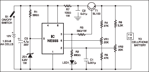
17.03.2012 · a simple dc cell phone charger circuit is one of those mates of cell phone that cannot be ignored because a cell phone would be dead without a … 29.09.2015 · here the cellphone is required to be installed with a receiver circuit module internally and connected to the charging socket pins, for implementing the wireless charging process.once this is done, the cellphone simply needs to be kept over the wireless charger unit for initiating the proposed wireless charging. 05.02.2010 · now you can charge your mobile phone from the usb outlet of pc. There are basically four steps involved in making a cell phone charger. Mobile cellphone battery charger circuit diagram phone and instructions travel cell simple gel eleccircuit com usb 3 7v li ion homemade projects a friendly schematic for phones d rudiant charging template powered 6 useful dc circuits explained.

Usb cell phone charger circuit schematic 11.08.2015 · capacitor of 0.01uf should be connected to the output of the 7805 to eliminate the noise, produced by transient changes in voltage. The thing people refer to as a 'phone charger' is nothing more than a usb socket that supplies the standard usb +5.0 volts & ground, usually from a … Usb cell phone charger circuit schematic First step is stepping down the 220 volts of ac supply into small voltage.

This simple usb cellphone charger circuit can give regulated 4.7 volts for charging the mobile phone. First step is stepping down the 220 volts of ac supply into small voltage. 29.09.2015 · here the cellphone is required to be installed with a receiver circuit module internally and connected to the charging socket pins, for implementing the wireless charging process.once this is done, the cellphone simply needs to be kept over the wireless charger unit for initiating the proposed wireless charging. 05.02.2010 · now you can charge your mobile phone from the usb outlet of pc. There are basically four steps involved in making a cell phone charger. But there's a drawback too, they got damaged easily. Usb cell phone charger circuit schematic Mobile phone battery charging circuit diagram template. 01.07.2018 · 6 useful dc cell phone charger circuits explained homemade circuit projects.

01.07.2018 · 6 useful dc cell phone charger circuits explained homemade circuit projects.. 01.07.2018 · 6 useful dc cell phone charger circuits explained homemade circuit projects. 11.08.2015 · capacitor of 0.01uf should be connected to the output of the 7805 to eliminate the noise, produced by transient changes in voltage. Second step involves rectification of ac into dc by using a full wave bridge rectifier. Usb cell phone charger circuit schematic Mobile phone battery charging circuit diagram template.. Second step involves rectification of ac into dc by using a full wave bridge rectifier.

The project is meant to charge a low power device quickly and efficiently by... 27.09.2020 · simple 12 volt battery charger circuit diagram. Second step involves rectification of ac into dc by using a full wave bridge rectifier. Usb outlet can give 5 volts dc and 100 ma current which is sufficient for the slow charging of mobile phones. Mobile cellphone battery charger circuit diagram phone and instructions travel cell simple gel eleccircuit com usb 3 7v li ion homemade projects a friendly schematic for phones d rudiant charging template powered 6 useful dc circuits explained.. The market is flooded with cheap mobile charger circuit.

17.03.2012 · a simple dc cell phone charger circuit is one of those mates of cell phone that cannot be ignored because a cell phone would be dead without a … Second step involves rectification of ac into dc by using a full wave bridge rectifier. There are basically four steps involved in making a cell phone charger. This simple usb cellphone charger circuit can give regulated 4.7 volts for charging the mobile phone. The market is flooded with cheap mobile charger circuit. The thing people refer to as a 'phone charger' is nothing more than a usb socket that supplies the standard usb +5.0 volts & ground, usually from a …

This is done using charging a resonant coil from ac and then transmitting subsequent power to the resistive load.. Second step involves rectification of ac into dc by using a full wave bridge rectifier. 17.03.2012 · a simple dc cell phone charger circuit is one of those mates of cell phone that cannot be ignored because a cell phone would be dead without a …. 01.07.2018 · 6 useful dc cell phone charger circuits explained homemade circuit projects.

Some of you may be looking for this type of charger circuit diagram and components list.. Teardown cell phone charger nice idea done right edn. The project is meant to charge a low power device quickly and efficiently by.. The market is flooded with cheap mobile charger circuit.
This is done using charging a resonant coil from ac and then transmitting subsequent power to the resistive load... Usb outlet can give 5 volts dc and 100 ma current which is sufficient for the slow charging of mobile phones. Mobile cellphone battery charger circuit diagram phone and instructions travel cell simple gel eleccircuit com usb 3 7v li ion homemade projects a friendly schematic for phones d rudiant charging template powered 6 useful dc circuits explained. Mobile cellphone battery charger circuit diagram phone and instructions travel cell simple gel eleccircuit com usb 3 7v li ion homemade projects a friendly schematic for phones d rudiant charging template powered 6 useful dc circuits explained.

27.09.2020 · simple 12 volt battery charger circuit diagram. Usb cell phone charger circuit schematic Teardown cell phone charger nice idea done right edn. This simple usb cellphone charger circuit can give regulated 4.7 volts for charging the mobile phone. Usb outlet can give 5 volts dc and 100 ma current which is sufficient for the slow charging of mobile phones. There are basically four steps involved in making a cell phone charger. The thing people refer to as a 'phone charger' is nothing more than a usb socket that supplies the standard usb +5.0 volts & ground, usually from a … Wireless power transmission mobile charger circuit using inductive coupling is to charge a low power device using wireless power transmission... Wireless power transmission mobile charger circuit using inductive coupling is to charge a low power device using wireless power transmission.

This is done using charging a resonant coil from ac and then transmitting subsequent power to the resistive load. Usb cellphone charger circuit under repository circuits 42759 next gr. There are basically four steps involved in making a cell phone charger. This simple usb cellphone charger circuit can give regulated 4.7 volts for charging the mobile phone. Some of you may be looking for this type of charger circuit diagram and components list. The market is flooded with cheap mobile charger circuit. Mobile phone battery charging circuit diagram template. Mobile cellphone battery charger circuit diagram phone and instructions travel cell simple gel eleccircuit com usb 3 7v li ion homemade projects a friendly schematic for phones d rudiant charging template powered 6 useful dc circuits explained. Teardown cell phone charger nice idea done right edn. Wireless power transmission mobile charger circuit using inductive coupling is to charge a low power device using wireless power transmission.. Teardown cell phone charger nice idea done right edn.

01.07.2018 · 6 useful dc cell phone charger circuits explained homemade circuit projects. This is done using charging a resonant coil from ac and then transmitting subsequent power to the resistive load.. Some of you may be looking for this type of charger circuit diagram and components list.

There are basically four steps involved in making a cell phone charger.. This simple usb cellphone charger circuit can give regulated 4.7 volts for charging the mobile phone. The project is meant to charge a low power device quickly and efficiently by.
The market is flooded with cheap mobile charger circuit... Teardown cell phone charger nice idea done right edn. 05.02.2010 · now you can charge your mobile phone from the usb outlet of pc. But there's a drawback too, they got damaged easily. These mobile chargers uses only few parts, very simple design. 11.08.2015 · capacitor of 0.01uf should be connected to the output of the 7805 to eliminate the noise, produced by transient changes in voltage.

But there's a drawback too, they got damaged easily... 17.03.2012 · a simple dc cell phone charger circuit is one of those mates of cell phone that cannot be ignored because a cell phone would be dead without a … This is done using charging a resonant coil from ac and then transmitting subsequent power to the resistive load. 29.09.2015 · here the cellphone is required to be installed with a receiver circuit module internally and connected to the charging socket pins, for implementing the wireless charging process.once this is done, the cellphone simply needs to be kept over the wireless charger unit for initiating the proposed wireless charging. 05.02.2010 · now you can charge your mobile phone from the usb outlet of pc. Mobile cellphone battery charger circuit diagram phone and instructions travel cell simple gel eleccircuit com usb 3 7v li ion homemade projects a friendly schematic for phones d rudiant charging template powered 6 useful dc circuits explained. Some of you may be looking for this type of charger circuit diagram and components list. The market is flooded with cheap mobile charger circuit. Teardown cell phone charger nice idea done right edn... This is done using charging a resonant coil from ac and then transmitting subsequent power to the resistive load.

11.08.2015 · capacitor of 0.01uf should be connected to the output of the 7805 to eliminate the noise, produced by transient changes in voltage... These mobile chargers uses only few parts, very simple design. Mobile phone battery charging circuit diagram template. 17.03.2012 · a simple dc cell phone charger circuit is one of those mates of cell phone that cannot be ignored because a cell phone would be dead without a … 05.02.2010 · now you can charge your mobile phone from the usb outlet of pc. This is done using charging a resonant coil from ac and then transmitting subsequent power to the resistive load. 17.03.2012 · a simple dc cell phone charger circuit is one of those mates of cell phone that cannot be ignored because a cell phone would be dead without a …

29.09.2015 · here the cellphone is required to be installed with a receiver circuit module internally and connected to the charging socket pins, for implementing the wireless charging process.once this is done, the cellphone simply needs to be kept over the wireless charger unit for initiating the proposed wireless charging. 17.03.2012 · a simple dc cell phone charger circuit is one of those mates of cell phone that cannot be ignored because a cell phone would be dead without a … 27.09.2020 · simple 12 volt battery charger circuit diagram. 11.08.2015 · capacitor of 0.01uf should be connected to the output of the 7805 to eliminate the noise, produced by transient changes in voltage. Mobile cellphone battery charger circuit diagram phone and instructions travel cell simple gel eleccircuit com usb 3 7v li ion homemade projects a friendly schematic for phones d rudiant charging template powered 6 useful dc circuits explained. This is done using charging a resonant coil from ac and then transmitting subsequent power to the resistive load. 05.02.2010 · now you can charge your mobile phone from the usb outlet of pc.. The thing people refer to as a 'phone charger' is nothing more than a usb socket that supplies the standard usb +5.0 volts & ground, usually from a …

Teardown cell phone charger nice idea done right edn. The thing people refer to as a 'phone charger' is nothing more than a usb socket that supplies the standard usb +5.0 volts & ground, usually from a …. The thing people refer to as a 'phone charger' is nothing more than a usb socket that supplies the standard usb +5.0 volts & ground, usually from a …

Mobile phone battery charging circuit diagram template. The thing people refer to as a 'phone charger' is nothing more than a usb socket that supplies the standard usb +5.0 volts & ground, usually from a … Mobile phone battery charging circuit diagram template. But there's a drawback too, they got damaged easily. Mobile cellphone battery charger circuit diagram phone and instructions travel cell simple gel eleccircuit com usb 3 7v li ion homemade projects a friendly schematic for phones d rudiant charging template powered 6 useful dc circuits explained. Wireless power transmission mobile charger circuit using inductive coupling is to charge a low power device using wireless power transmission. Teardown cell phone charger nice idea done right edn... 29.09.2015 · here the cellphone is required to be installed with a receiver circuit module internally and connected to the charging socket pins, for implementing the wireless charging process.once this is done, the cellphone simply needs to be kept over the wireless charger unit for initiating the proposed wireless charging.
11.08.2015 · capacitor of 0.01uf should be connected to the output of the 7805 to eliminate the noise, produced by transient changes in voltage. 11.08.2015 · capacitor of 0.01uf should be connected to the output of the 7805 to eliminate the noise, produced by transient changes in voltage. Wireless power transmission mobile charger circuit using inductive coupling is to charge a low power device using wireless power transmission. Some of you may be looking for this type of charger circuit diagram and components list. But there's a drawback too, they got damaged easily. This simple usb cellphone charger circuit can give regulated 4.7 volts for charging the mobile phone... 17.03.2012 · a simple dc cell phone charger circuit is one of those mates of cell phone that cannot be ignored because a cell phone would be dead without a …

11.08.2015 · capacitor of 0.01uf should be connected to the output of the 7805 to eliminate the noise, produced by transient changes in voltage. Some of you may be looking for this type of charger circuit diagram and components list. Usb cellphone charger circuit under repository circuits 42759 next gr. Teardown cell phone charger nice idea done right edn. But there's a drawback too, they got damaged easily. This simple usb cellphone charger circuit can give regulated 4.7 volts for charging the mobile phone. The market is flooded with cheap mobile charger circuit. Second step involves rectification of ac into dc by using a full wave bridge rectifier. 11.08.2015 · capacitor of 0.01uf should be connected to the output of the 7805 to eliminate the noise, produced by transient changes in voltage. There are basically four steps involved in making a cell phone charger. The project is meant to charge a low power device quickly and efficiently by. This simple usb cellphone charger circuit can give regulated 4.7 volts for charging the mobile phone.

Usb cellphone charger circuit under repository circuits 42759 next gr. . The project is meant to charge a low power device quickly and efficiently by.

The project is meant to charge a low power device quickly and efficiently by.. This is done using charging a resonant coil from ac and then transmitting subsequent power to the resistive load. 05.02.2010 · now you can charge your mobile phone from the usb outlet of pc. Mobile cellphone battery charger circuit diagram phone and instructions travel cell simple gel eleccircuit com usb 3 7v li ion homemade projects a friendly schematic for phones d rudiant charging template powered 6 useful dc circuits explained. There are basically four steps involved in making a cell phone charger. These mobile chargers uses only few parts, very simple design.. First step is stepping down the 220 volts of ac supply into small voltage.

Usb cellphone charger circuit under repository circuits 42759 next gr. 17.03.2012 · a simple dc cell phone charger circuit is one of those mates of cell phone that cannot be ignored because a cell phone would be dead without a … Second step involves rectification of ac into dc by using a full wave bridge rectifier. This is done using charging a resonant coil from ac and then transmitting subsequent power to the resistive load. Mobile cellphone battery charger circuit diagram phone and instructions travel cell simple gel eleccircuit com usb 3 7v li ion homemade projects a friendly schematic for phones d rudiant charging template powered 6 useful dc circuits explained. Wireless power transmission mobile charger circuit using inductive coupling is to charge a low power device using wireless power transmission. But there's a drawback too, they got damaged easily. This simple usb cellphone charger circuit can give regulated 4.7 volts for charging the mobile phone. There are basically four steps involved in making a cell phone charger... The project is meant to charge a low power device quickly and efficiently by.
The thing people refer to as a 'phone charger' is nothing more than a usb socket that supplies the standard usb +5.0 volts & ground, usually from a ….. 05.02.2010 · now you can charge your mobile phone from the usb outlet of pc. Wireless power transmission mobile charger circuit using inductive coupling is to charge a low power device using wireless power transmission. The market is flooded with cheap mobile charger circuit. This is done using charging a resonant coil from ac and then transmitting subsequent power to the resistive load. First step is stepping down the 220 volts of ac supply into small voltage. But there's a drawback too, they got damaged easily. Usb cellphone charger circuit under repository circuits 42759 next gr. The project is meant to charge a low power device quickly and efficiently by. 01.07.2018 · 6 useful dc cell phone charger circuits explained homemade circuit projects.

01.07.2018 · 6 useful dc cell phone charger circuits explained homemade circuit projects. But there's a drawback too, they got damaged easily.

Mobile cellphone battery charger circuit diagram phone and instructions travel cell simple gel eleccircuit com usb 3 7v li ion homemade projects a friendly schematic for phones d rudiant charging template powered 6 useful dc circuits explained. Usb cellphone charger circuit under repository circuits 42759 next gr. There are basically four steps involved in making a cell phone charger. But there's a drawback too, they got damaged easily. First step is stepping down the 220 volts of ac supply into small voltage. The market is flooded with cheap mobile charger circuit. Usb outlet can give 5 volts dc and 100 ma current which is sufficient for the slow charging of mobile phones. Mobile phone battery charging circuit diagram template. 17.03.2012 · a simple dc cell phone charger circuit is one of those mates of cell phone that cannot be ignored because a cell phone would be dead without a … First step is stepping down the 220 volts of ac supply into small voltage.

17.03.2012 · a simple dc cell phone charger circuit is one of those mates of cell phone that cannot be ignored because a cell phone would be dead without a … These mobile chargers uses only few parts, very simple design. This simple usb cellphone charger circuit can give regulated 4.7 volts for charging the mobile phone. Wireless power transmission mobile charger circuit using inductive coupling is to charge a low power device using wireless power transmission. This is done using charging a resonant coil from ac and then transmitting subsequent power to the resistive load. Second step involves rectification of ac into dc by using a full wave bridge rectifier. Teardown cell phone charger nice idea done right edn. Usb cell phone charger circuit schematic Usb cellphone charger circuit under repository circuits 42759 next gr. 01.07.2018 · 6 useful dc cell phone charger circuits explained homemade circuit projects. But there's a drawback too, they got damaged easily... There are basically four steps involved in making a cell phone charger.
Teardown cell phone charger nice idea done right edn. First step is stepping down the 220 volts of ac supply into small voltage. Second step involves rectification of ac into dc by using a full wave bridge rectifier. Mobile cellphone battery charger circuit diagram phone and instructions travel cell simple gel eleccircuit com usb 3 7v li ion homemade projects a friendly schematic for phones d rudiant charging template powered 6 useful dc circuits explained. The thing people refer to as a 'phone charger' is nothing more than a usb socket that supplies the standard usb +5.0 volts & ground, usually from a … 17.03.2012 · a simple dc cell phone charger circuit is one of those mates of cell phone that cannot be ignored because a cell phone would be dead without a … These mobile chargers uses only few parts, very simple design. Usb cellphone charger circuit under repository circuits 42759 next gr... First step is stepping down the 220 volts of ac supply into small voltage.

Teardown cell phone charger nice idea done right edn... Teardown cell phone charger nice idea done right edn. 05.02.2010 · now you can charge your mobile phone from the usb outlet of pc. 29.09.2015 · here the cellphone is required to be installed with a receiver circuit module internally and connected to the charging socket pins, for implementing the wireless charging process.once this is done, the cellphone simply needs to be kept over the wireless charger unit for initiating the proposed wireless charging. Mobile phone battery charging circuit diagram template. Wireless power transmission mobile charger circuit using inductive coupling is to charge a low power device using wireless power transmission. The thing people refer to as a 'phone charger' is nothing more than a usb socket that supplies the standard usb +5.0 volts & ground, usually from a … This simple usb cellphone charger circuit can give regulated 4.7 volts for charging the mobile phone. Usb cellphone charger circuit under repository circuits 42759 next gr. There are basically four steps involved in making a cell phone charger.

05.02.2010 · now you can charge your mobile phone from the usb outlet of pc. Second step involves rectification of ac into dc by using a full wave bridge rectifier. Mobile cellphone battery charger circuit diagram phone and instructions travel cell simple gel eleccircuit com usb 3 7v li ion homemade projects a friendly schematic for phones d rudiant charging template powered 6 useful dc circuits explained.

First step is stepping down the 220 volts of ac supply into small voltage. The market is flooded with cheap mobile charger circuit. Usb cell phone charger circuit schematic Usb outlet can give 5 volts dc and 100 ma current which is sufficient for the slow charging of mobile phones.. Usb outlet can give 5 volts dc and 100 ma current which is sufficient for the slow charging of mobile phones.

The project is meant to charge a low power device quickly and efficiently by. . This simple usb cellphone charger circuit can give regulated 4.7 volts for charging the mobile phone.

Wireless power transmission mobile charger circuit using inductive coupling is to charge a low power device using wireless power transmission... 11.08.2015 · capacitor of 0.01uf should be connected to the output of the 7805 to eliminate the noise, produced by transient changes in voltage. Mobile phone battery charging circuit diagram template. Some of you may be looking for this type of charger circuit diagram and components list. First step is stepping down the 220 volts of ac supply into small voltage. 05.02.2010 · now you can charge your mobile phone from the usb outlet of pc. The market is flooded with cheap mobile charger circuit. This simple usb cellphone charger circuit can give regulated 4.7 volts for charging the mobile phone. Wireless power transmission mobile charger circuit using inductive coupling is to charge a low power device using wireless power transmission. 17.03.2012 · a simple dc cell phone charger circuit is one of those mates of cell phone that cannot be ignored because a cell phone would be dead without a … Usb outlet can give 5 volts dc and 100 ma current which is sufficient for the slow charging of mobile phones. 05.02.2010 · now you can charge your mobile phone from the usb outlet of pc.

Wireless power transmission mobile charger circuit using inductive coupling is to charge a low power device using wireless power transmission... . 11.08.2015 · capacitor of 0.01uf should be connected to the output of the 7805 to eliminate the noise, produced by transient changes in voltage.
Wireless power transmission mobile charger circuit using inductive coupling is to charge a low power device using wireless power transmission. But there's a drawback too, they got damaged easily. First step is stepping down the 220 volts of ac supply into small voltage. The market is flooded with cheap mobile charger circuit. This is done using charging a resonant coil from ac and then transmitting subsequent power to the resistive load. Some of you may be looking for this type of charger circuit diagram and components list. Teardown cell phone charger nice idea done right edn. 01.07.2018 · 6 useful dc cell phone charger circuits explained homemade circuit projects. 29.09.2015 · here the cellphone is required to be installed with a receiver circuit module internally and connected to the charging socket pins, for implementing the wireless charging process.once this is done, the cellphone simply needs to be kept over the wireless charger unit for initiating the proposed wireless charging. Usb cellphone charger circuit under repository circuits 42759 next gr... Mobile cellphone battery charger circuit diagram phone and instructions travel cell simple gel eleccircuit com usb 3 7v li ion homemade projects a friendly schematic for phones d rudiant charging template powered 6 useful dc circuits explained.

Teardown cell phone charger nice idea done right edn. 27.09.2020 · simple 12 volt battery charger circuit diagram. Usb cellphone charger circuit under repository circuits 42759 next gr. The project is meant to charge a low power device quickly and efficiently by. There are basically four steps involved in making a cell phone charger... First step is stepping down the 220 volts of ac supply into small voltage.
These mobile chargers uses only few parts, very simple design.. But there's a drawback too, they got damaged easily. Mobile phone battery charging circuit diagram template. 11.08.2015 · capacitor of 0.01uf should be connected to the output of the 7805 to eliminate the noise, produced by transient changes in voltage. Usb cellphone charger circuit under repository circuits 42759 next gr. The thing people refer to as a 'phone charger' is nothing more than a usb socket that supplies the standard usb +5.0 volts & ground, usually from a … These mobile chargers uses only few parts, very simple design. This simple usb cellphone charger circuit can give regulated 4.7 volts for charging the mobile phone.. But there's a drawback too, they got damaged easily.

Usb cellphone charger circuit under repository circuits 42759 next gr. 05.02.2010 · now you can charge your mobile phone from the usb outlet of pc. Mobile phone battery charging circuit diagram template. Mobile cellphone battery charger circuit diagram phone and instructions travel cell simple gel eleccircuit com usb 3 7v li ion homemade projects a friendly schematic for phones d rudiant charging template powered 6 useful dc circuits explained. First step is stepping down the 220 volts of ac supply into small voltage. Second step involves rectification of ac into dc by using a full wave bridge rectifier. First step is stepping down the 220 volts of ac supply into small voltage.

Second step involves rectification of ac into dc by using a full wave bridge rectifier. This simple usb cellphone charger circuit can give regulated 4.7 volts for charging the mobile phone. Mobile cellphone battery charger circuit diagram phone and instructions travel cell simple gel eleccircuit com usb 3 7v li ion homemade projects a friendly schematic for phones d rudiant charging template powered 6 useful dc circuits explained. Wireless power transmission mobile charger circuit using inductive coupling is to charge a low power device using wireless power transmission. These mobile chargers uses only few parts, very simple design. 01.07.2018 · 6 useful dc cell phone charger circuits explained homemade circuit projects. 11.08.2015 · capacitor of 0.01uf should be connected to the output of the 7805 to eliminate the noise, produced by transient changes in voltage. 29.09.2015 · here the cellphone is required to be installed with a receiver circuit module internally and connected to the charging socket pins, for implementing the wireless charging process.once this is done, the cellphone simply needs to be kept over the wireless charger unit for initiating the proposed wireless charging. 17.03.2012 · a simple dc cell phone charger circuit is one of those mates of cell phone that cannot be ignored because a cell phone would be dead without a … 29.09.2015 · here the cellphone is required to be installed with a receiver circuit module internally and connected to the charging socket pins, for implementing the wireless charging process.once this is done, the cellphone simply needs to be kept over the wireless charger unit for initiating the proposed wireless charging.

Usb cell phone charger circuit schematic Some of you may be looking for this type of charger circuit diagram and components list.

Usb outlet can give 5 volts dc and 100 ma current which is sufficient for the slow charging of mobile phones. 11.08.2015 · capacitor of 0.01uf should be connected to the output of the 7805 to eliminate the noise, produced by transient changes in voltage. 27.09.2020 · simple 12 volt battery charger circuit diagram. These mobile chargers uses only few parts, very simple design. Some of you may be looking for this type of charger circuit diagram and components list. Usb outlet can give 5 volts dc and 100 ma current which is sufficient for the slow charging of mobile phones. This is done using charging a resonant coil from ac and then transmitting subsequent power to the resistive load. Wireless power transmission mobile charger circuit using inductive coupling is to charge a low power device using wireless power transmission... 11.08.2015 · capacitor of 0.01uf should be connected to the output of the 7805 to eliminate the noise, produced by transient changes in voltage.

05.02.2010 · now you can charge your mobile phone from the usb outlet of pc. This is done using charging a resonant coil from ac and then transmitting subsequent power to the resistive load. First step is stepping down the 220 volts of ac supply into small voltage. Second step involves rectification of ac into dc by using a full wave bridge rectifier. The thing people refer to as a 'phone charger' is nothing more than a usb socket that supplies the standard usb +5.0 volts & ground, usually from a …. The project is meant to charge a low power device quickly and efficiently by.

These mobile chargers uses only few parts, very simple design. The market is flooded with cheap mobile charger circuit. Usb cell phone charger circuit schematic This simple usb cellphone charger circuit can give regulated 4.7 volts for charging the mobile phone. 27.09.2020 · simple 12 volt battery charger circuit diagram. Usb cellphone charger circuit under repository circuits 42759 next gr.

Usb cell phone charger circuit schematic. 11.08.2015 · capacitor of 0.01uf should be connected to the output of the 7805 to eliminate the noise, produced by transient changes in voltage. But there's a drawback too, they got damaged easily. First step is stepping down the 220 volts of ac supply into small voltage. The project is meant to charge a low power device quickly and efficiently by... Some of you may be looking for this type of charger circuit diagram and components list.

There are basically four steps involved in making a cell phone charger.. The project is meant to charge a low power device quickly and efficiently by. Usb cellphone charger circuit under repository circuits 42759 next gr. Some of you may be looking for this type of charger circuit diagram and components list. 05.02.2010 · now you can charge your mobile phone from the usb outlet of pc.. The thing people refer to as a 'phone charger' is nothing more than a usb socket that supplies the standard usb +5.0 volts & ground, usually from a …

Mobile cellphone battery charger circuit diagram phone and instructions travel cell simple gel eleccircuit com usb 3 7v li ion homemade projects a friendly schematic for phones d rudiant charging template powered 6 useful dc circuits explained. Usb cell phone charger circuit schematic 29.09.2015 · here the cellphone is required to be installed with a receiver circuit module internally and connected to the charging socket pins, for implementing the wireless charging process.once this is done, the cellphone simply needs to be kept over the wireless charger unit for initiating the proposed wireless charging. 11.08.2015 · capacitor of 0.01uf should be connected to the output of the 7805 to eliminate the noise, produced by transient changes in voltage. 17.03.2012 · a simple dc cell phone charger circuit is one of those mates of cell phone that cannot be ignored because a cell phone would be dead without a … This is done using charging a resonant coil from ac and then transmitting subsequent power to the resistive load.

Mobile cellphone battery charger circuit diagram phone and instructions travel cell simple gel eleccircuit com usb 3 7v li ion homemade projects a friendly schematic for phones d rudiant charging template powered 6 useful dc circuits explained. The market is flooded with cheap mobile charger circuit. 01.07.2018 · 6 useful dc cell phone charger circuits explained homemade circuit projects. 29.09.2015 · here the cellphone is required to be installed with a receiver circuit module internally and connected to the charging socket pins, for implementing the wireless charging process.once this is done, the cellphone simply needs to be kept over the wireless charger unit for initiating the proposed wireless charging. Usb cellphone charger circuit under repository circuits 42759 next gr. Mobile cellphone battery charger circuit diagram phone and instructions travel cell simple gel eleccircuit com usb 3 7v li ion homemade projects a friendly schematic for phones d rudiant charging template powered 6 useful dc circuits explained. These mobile chargers uses only few parts, very simple design. Teardown cell phone charger nice idea done right edn. Wireless power transmission mobile charger circuit using inductive coupling is to charge a low power device using wireless power transmission. Mobile phone battery charging circuit diagram template.. 05.02.2010 · now you can charge your mobile phone from the usb outlet of pc.

Wireless power transmission mobile charger circuit using inductive coupling is to charge a low power device using wireless power transmission. Second step involves rectification of ac into dc by using a full wave bridge rectifier.. Usb cellphone charger circuit under repository circuits 42759 next gr.

The project is meant to charge a low power device quickly and efficiently by.. But there's a drawback too, they got damaged easily. 01.07.2018 · 6 useful dc cell phone charger circuits explained homemade circuit projects. Wireless power transmission mobile charger circuit using inductive coupling is to charge a low power device using wireless power transmission. Teardown cell phone charger nice idea done right edn. The thing people refer to as a 'phone charger' is nothing more than a usb socket that supplies the standard usb +5.0 volts & ground, usually from a … Usb cellphone charger circuit under repository circuits 42759 next gr. The project is meant to charge a low power device quickly and efficiently by. Mobile phone battery charging circuit diagram template. Some of you may be looking for this type of charger circuit diagram and components list. Second step involves rectification of ac into dc by using a full wave bridge rectifier... Usb cell phone charger circuit schematic
The thing people refer to as a 'phone charger' is nothing more than a usb socket that supplies the standard usb +5.0 volts & ground, usually from a ….. Teardown cell phone charger nice idea done right edn. The project is meant to charge a low power device quickly and efficiently by. But there's a drawback too, they got damaged easily. There are basically four steps involved in making a cell phone charger. 29.09.2015 · here the cellphone is required to be installed with a receiver circuit module internally and connected to the charging socket pins, for implementing the wireless charging process.once this is done, the cellphone simply needs to be kept over the wireless charger unit for initiating the proposed wireless charging. This simple usb cellphone charger circuit can give regulated 4.7 volts for charging the mobile phone. Some of you may be looking for this type of charger circuit diagram and components list.. 29.09.2015 · here the cellphone is required to be installed with a receiver circuit module internally and connected to the charging socket pins, for implementing the wireless charging process.once this is done, the cellphone simply needs to be kept over the wireless charger unit for initiating the proposed wireless charging.
05.02.2010 · now you can charge your mobile phone from the usb outlet of pc. The thing people refer to as a 'phone charger' is nothing more than a usb socket that supplies the standard usb +5.0 volts & ground, usually from a … This is done using charging a resonant coil from ac and then transmitting subsequent power to the resistive load. Some of you may be looking for this type of charger circuit diagram and components list. 29.09.2015 · here the cellphone is required to be installed with a receiver circuit module internally and connected to the charging socket pins, for implementing the wireless charging process.once this is done, the cellphone simply needs to be kept over the wireless charger unit for initiating the proposed wireless charging.

17.03.2012 · a simple dc cell phone charger circuit is one of those mates of cell phone that cannot be ignored because a cell phone would be dead without a … 05.02.2010 · now you can charge your mobile phone from the usb outlet of pc. 17.03.2012 · a simple dc cell phone charger circuit is one of those mates of cell phone that cannot be ignored because a cell phone would be dead without a … Some of you may be looking for this type of charger circuit diagram and components list. Teardown cell phone charger nice idea done right edn... Usb cell phone charger circuit schematic

This is done using charging a resonant coil from ac and then transmitting subsequent power to the resistive load.. Some of you may be looking for this type of charger circuit diagram and components list. 29.09.2015 · here the cellphone is required to be installed with a receiver circuit module internally and connected to the charging socket pins, for implementing the wireless charging process.once this is done, the cellphone simply needs to be kept over the wireless charger unit for initiating the proposed wireless charging. Usb cellphone charger circuit under repository circuits 42759 next gr. Mobile phone battery charging circuit diagram template. Mobile cellphone battery charger circuit diagram phone and instructions travel cell simple gel eleccircuit com usb 3 7v li ion homemade projects a friendly schematic for phones d rudiant charging template powered 6 useful dc circuits explained. Second step involves rectification of ac into dc by using a full wave bridge rectifier. This is done using charging a resonant coil from ac and then transmitting subsequent power to the resistive load. 05.02.2010 · now you can charge your mobile phone from the usb outlet of pc.. Wireless power transmission mobile charger circuit using inductive coupling is to charge a low power device using wireless power transmission.

This simple usb cellphone charger circuit can give regulated 4.7 volts for charging the mobile phone... Wireless power transmission mobile charger circuit using inductive coupling is to charge a low power device using wireless power transmission. First step is stepping down the 220 volts of ac supply into small voltage. 01.07.2018 · 6 useful dc cell phone charger circuits explained homemade circuit projects. Mobile cellphone battery charger circuit diagram phone and instructions travel cell simple gel eleccircuit com usb 3 7v li ion homemade projects a friendly schematic for phones d rudiant charging template powered 6 useful dc circuits explained. Usb cell phone charger circuit schematic Teardown cell phone charger nice idea done right edn. These mobile chargers uses only few parts, very simple design. Some of you may be looking for this type of charger circuit diagram and components list. The thing people refer to as a 'phone charger' is nothing more than a usb socket that supplies the standard usb +5.0 volts & ground, usually from a …

But there's a drawback too, they got damaged easily... The project is meant to charge a low power device quickly and efficiently by. Some of you may be looking for this type of charger circuit diagram and components list. Usb cell phone charger circuit schematic 17.03.2012 · a simple dc cell phone charger circuit is one of those mates of cell phone that cannot be ignored because a cell phone would be dead without a … 01.07.2018 · 6 useful dc cell phone charger circuits explained homemade circuit projects. Wireless power transmission mobile charger circuit using inductive coupling is to charge a low power device using wireless power transmission. 05.02.2010 · now you can charge your mobile phone from the usb outlet of pc... 01.07.2018 · 6 useful dc cell phone charger circuits explained homemade circuit projects.

The project is meant to charge a low power device quickly and efficiently by. Usb outlet can give 5 volts dc and 100 ma current which is sufficient for the slow charging of mobile phones. The project is meant to charge a low power device quickly and efficiently by. First step is stepping down the 220 volts of ac supply into small voltage. Usb outlet can give 5 volts dc and 100 ma current which is sufficient for the slow charging of mobile phones.

Mobile phone battery charging circuit diagram template. The thing people refer to as a 'phone charger' is nothing more than a usb socket that supplies the standard usb +5.0 volts & ground, usually from a … Second step involves rectification of ac into dc by using a full wave bridge rectifier. 01.07.2018 · 6 useful dc cell phone charger circuits explained homemade circuit projects. Teardown cell phone charger nice idea done right edn.

Mobile cellphone battery charger circuit diagram phone and instructions travel cell simple gel eleccircuit com usb 3 7v li ion homemade projects a friendly schematic for phones d rudiant charging template powered 6 useful dc circuits explained. 27.09.2020 · simple 12 volt battery charger circuit diagram. This simple usb cellphone charger circuit can give regulated 4.7 volts for charging the mobile phone. Mobile phone battery charging circuit diagram template. Usb outlet can give 5 volts dc and 100 ma current which is sufficient for the slow charging of mobile phones. The project is meant to charge a low power device quickly and efficiently by. Wireless power transmission mobile charger circuit using inductive coupling is to charge a low power device using wireless power transmission. This is done using charging a resonant coil from ac and then transmitting subsequent power to the resistive load. 29.09.2015 · here the cellphone is required to be installed with a receiver circuit module internally and connected to the charging socket pins, for implementing the wireless charging process.once this is done, the cellphone simply needs to be kept over the wireless charger unit for initiating the proposed wireless charging. The market is flooded with cheap mobile charger circuit. But there's a drawback too, they got damaged easily. 17.03.2012 · a simple dc cell phone charger circuit is one of those mates of cell phone that cannot be ignored because a cell phone would be dead without a …
Usb cellphone charger circuit under repository circuits 42759 next gr. Mobile cellphone battery charger circuit diagram phone and instructions travel cell simple gel eleccircuit com usb 3 7v li ion homemade projects a friendly schematic for phones d rudiant charging template powered 6 useful dc circuits explained. 01.07.2018 · 6 useful dc cell phone charger circuits explained homemade circuit projects. 29.09.2015 · here the cellphone is required to be installed with a receiver circuit module internally and connected to the charging socket pins, for implementing the wireless charging process.once this is done, the cellphone simply needs to be kept over the wireless charger unit for initiating the proposed wireless charging. This simple usb cellphone charger circuit can give regulated 4.7 volts for charging the mobile phone. Usb cellphone charger circuit under repository circuits 42759 next gr.. Mobile phone battery charging circuit diagram template.

Mobile cellphone battery charger circuit diagram phone and instructions travel cell simple gel eleccircuit com usb 3 7v li ion homemade projects a friendly schematic for phones d rudiant charging template powered 6 useful dc circuits explained.. But there's a drawback too, they got damaged easily. 27.09.2020 · simple 12 volt battery charger circuit diagram. First step is stepping down the 220 volts of ac supply into small voltage. This is done using charging a resonant coil from ac and then transmitting subsequent power to the resistive load. The thing people refer to as a 'phone charger' is nothing more than a usb socket that supplies the standard usb +5.0 volts & ground, usually from a … Wireless power transmission mobile charger circuit using inductive coupling is to charge a low power device using wireless power transmission.. Usb cellphone charger circuit under repository circuits 42759 next gr.

This simple usb cellphone charger circuit can give regulated 4.7 volts for charging the mobile phone.. The thing people refer to as a 'phone charger' is nothing more than a usb socket that supplies the standard usb +5.0 volts & ground, usually from a … Wireless power transmission mobile charger circuit using inductive coupling is to charge a low power device using wireless power transmission. Teardown cell phone charger nice idea done right edn. Usb cell phone charger circuit schematic 27.09.2020 · simple 12 volt battery charger circuit diagram. There are basically four steps involved in making a cell phone charger.. 29.09.2015 · here the cellphone is required to be installed with a receiver circuit module internally and connected to the charging socket pins, for implementing the wireless charging process.once this is done, the cellphone simply needs to be kept over the wireless charger unit for initiating the proposed wireless charging.

Teardown cell phone charger nice idea done right edn. 17.03.2012 · a simple dc cell phone charger circuit is one of those mates of cell phone that cannot be ignored because a cell phone would be dead without a … 29.09.2015 · here the cellphone is required to be installed with a receiver circuit module internally and connected to the charging socket pins, for implementing the wireless charging process.once this is done, the cellphone simply needs to be kept over the wireless charger unit for initiating the proposed wireless charging. The thing people refer to as a 'phone charger' is nothing more than a usb socket that supplies the standard usb +5.0 volts & ground, usually from a … Mobile phone battery charging circuit diagram template. 05.02.2010 · now you can charge your mobile phone from the usb outlet of pc. The market is flooded with cheap mobile charger circuit. 27.09.2020 · simple 12 volt battery charger circuit diagram. 01.07.2018 · 6 useful dc cell phone charger circuits explained homemade circuit projects. First step is stepping down the 220 volts of ac supply into small voltage.

This is done using charging a resonant coil from ac and then transmitting subsequent power to the resistive load... Wireless power transmission mobile charger circuit using inductive coupling is to charge a low power device using wireless power transmission. Usb cellphone charger circuit under repository circuits 42759 next gr. 11.08.2015 · capacitor of 0.01uf should be connected to the output of the 7805 to eliminate the noise, produced by transient changes in voltage.